Week 13, Output Devices
This week assignment tasks are
is to measure something: add a sensor to a microcontroller board which was designed and built to read something.
add an output device to a microcontroller board and programmed it to do something
Output devices
Examples are:
LED, Lamp, Buzzer, Piezo, Motors, Solenoid, Relay, 7-segment display, etc
The signal output can be from a pin of a Attiny45 chip to activate any of the output device mentioned.
Design and Conceptualization
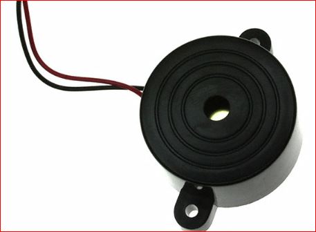
Buzzer and click link here for its datasheet.
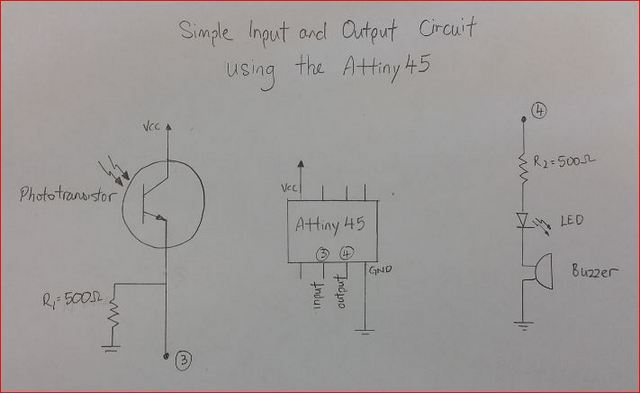
Although the supply is a 5VDC of an USB, the buzzer operating voltage is between 3V to 16V according the datasheet. That's the reason I'm using this buzzer device. I also added a LED to create visual indication that the output signal from the Attiny45 pin.
The design I'll be using is the same mentioned in Week 11.
The board I am using will have an input devices connected to the PCB and the same goes to the output pins terminal.
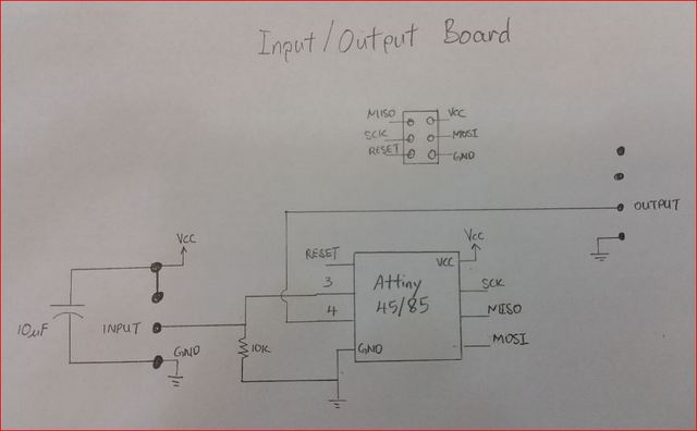
Simple input and output circuit sketch
Making the PCB
Below are the screen shots of the final input and output board.
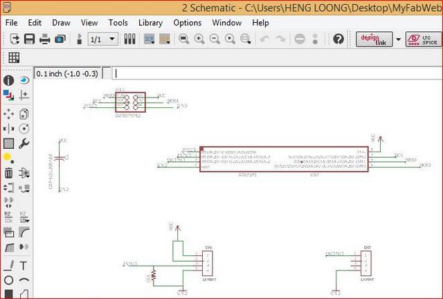
Schematic of the input and output circuit
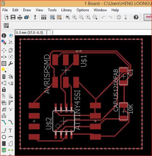
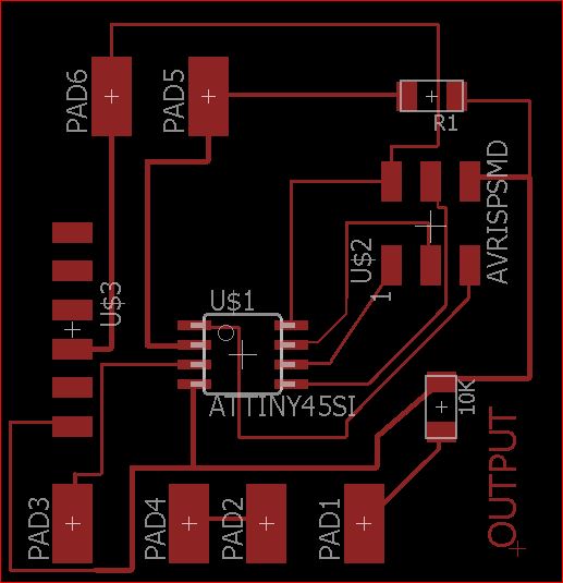
Layout of the input and output circuit components
The working files of schematic and board EagleCAD design can be downloaded here with a Right Click over them and "Save Link As".
Testing out
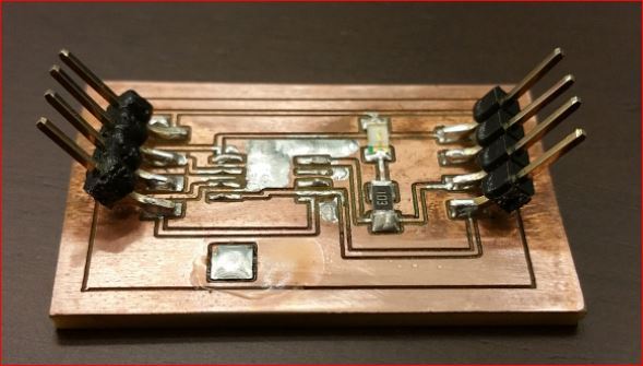
Faulty input and output pcb
Did another round of PCB routing but I removed the capacitor and resistor to reduce fault variables, performed continuity test, soldered on the components and found a short between a pin terminal and to the adjacent copper paths. These pictures below made me understanded the meaning of the straws tat broke the camel back.
Pins broke and destoyed the copper surfaces
I am doing it my way
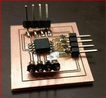
Followed up with the standard procedure of bootloader the Attiny45 chip and uploading the program into it. The final circuit would looked like as shown below.
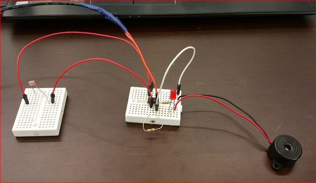
The video below showed the function of circuit.
The working files of Input and Output can be downloaded here with a Right Click over them and "Save Link As".
Making the Ouput PCB Board (Update)
The program was written in Arduino IDE and then the circuit was designed with EagleCAD before being milled out onto a PCB.
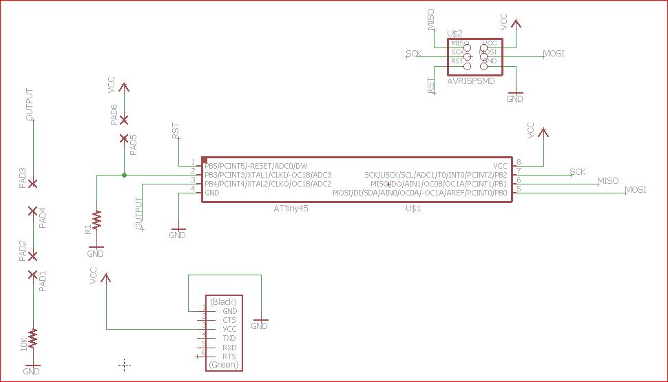
Output Schematic Drawing (Right click and save link as)
Input Board Drawing (Right click and save link as)
The programming file can be downloaded here.
The circuit was then milled out onto a PCB.
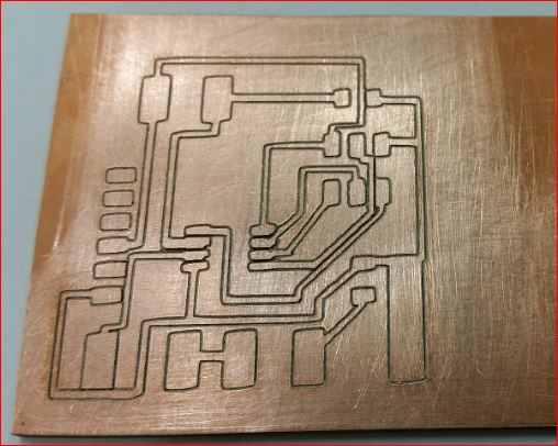
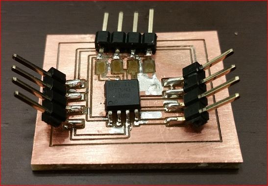
Output Device PCB
I ran into some problems when I tried to upload the program but I still can't resolved it. I got my colleague Mark to help me troubleshoot and he discovered there was a missing connect between PB2 of the Attiny45 to one of header pins. The missing connections were RX nd TX of the Attiny45 to the TX and RX connection of the serial board. Which in this case the Attiny45 TX to serial board RX was missing; indicated by a blue ring in the picture below.
It was a crucial connection when loading the program via FabISP but not when using Arduino as an ISP. I just added the connection with a wire for use later with a FabISP.
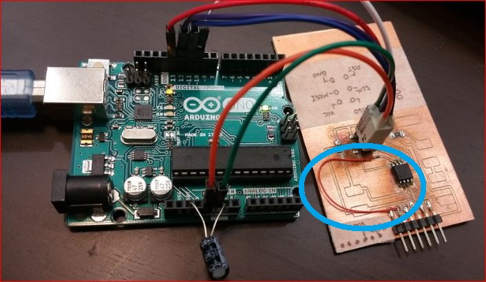
Toubleshooting the Output PCB
The PCB was then populated with components after the troubleshooting and loading of the program file.
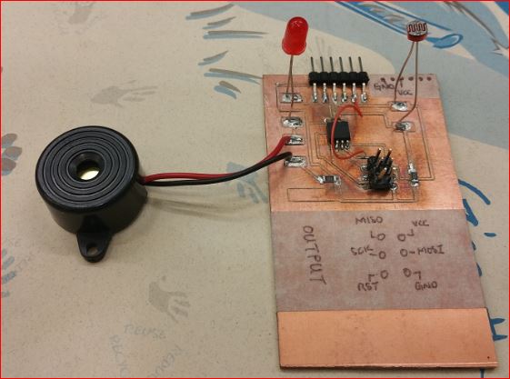
The video showed the output messages, buzzer and LED in relation to the status of the LDR sensor when it was covered and uncovered.